- 您现在的位置:买卖IC网 > Sheet目录1905 > ATMEGA8HVA-4CKU (Atmel)MCU AVR 8K FLASH 4MHZ 36-LGA
168
8024A–AVR–04/08
ATmega8HVA/16HVA
Notes:
1. All DC Characteristics contained in this data sheet are based on simulation and characterization of other AVR microcontrol-
lers manufactured in the same process technology. These values are preliminary values representing design targets, and
will be updated after characterization of actual silicon.
2. Voltage Regulator performance is based on 220 nF fly capacitors and 2.2 F smooth capacitor.
3. After VREF calibration at a second temperature. By default the first calibration is performed at temperature T
HOT in Atmel
factory test. The value of THOT is stored in the signature row. The second calibration step can easily be implemented in a
standard test flow at room temperature.
4. The measured V
PTAT voltage must be scaled with the calibration value stored in the VPTAT Calibration Register to get the
absolute temperature. The specified value represents target accuracy after Atmel factory calibration. Accuracy can be fur-
ther improved by doing a system calibration measurement at a well-known temperature.
5. This value is not tested in production.
6. After software offset compensation, using the polarity switching (CADPOL) feature.
7. After scaling of VADC raw data using Gain and Offset Calibration values stored in Signature Row.
8. Actual offset for each channel stored in signature row can be used to remove this offset error.
9. If the cell input needs to be measured when PV1 is below 1.5V, Atmel can provide data that facilitates less accurate mea-
surements in this range.
10. Actual frequency measured at Atmel factory stored in signature row.
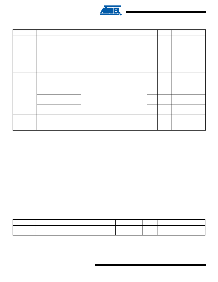
29.3
External Interrupt Characteristics
Coulomb
Counter
Reference Voltage
± 110
mV
Conversion Time
and Resolution(5)
26.9 V Resolution
3.9
ms
0.84 V Resolution
1000
ms
INL(5)
4LSB
CC-ADC Offset(5)(6)
2.5
± 15
LSB
Gain Error(3)
-100 mV < VPI - NI < 100 mV
± 0.1
± 1
%
Temperature
Sensor
V
PTAT, Voltage Proportional
to Absolute Temperature
0.67
mV/K
Absolute Accuracy(4)
Measured in Active mode
± 2
± 5
K
Slow RC
Oscillator(10)
Frequency
91
131
171
kHz
Frequency drift over
temperature(5)
1.5
%
Slow RC Frequency
predicion error(5)
1%
Ultra Low
Power RC
Oscillator(10)
Frequency
89
128
167
kHz
Frequency drift over
temperature(5)
6%
Table 29-1.
Electrical Characteristics
(1)(T
A = -10°C to 70°C unless otherwise specified) (Continued)
Parameter
Condition
Min
Typ
Max
Unit
Table 29-2.
Asynchronous External Interrupt Characteristics
Symbol
Parameter
Condition
Min
Typ
Max
Units
tINT
Minimum pulse width for asynchronous external
interrupt
50
ns
发布紧急采购,3分钟左右您将得到回复。
相关PDF资料
ATSAM3N4AA-AU
MCU FLASH 48-QFP
ATSAM3SD8CA-CU
IC MCU 2X256KB CORTEX-M3 100-QFN
ATSAM3U1EB-CU
IC MCU 64KB CORTEX-M3 144-TFBGA
ATSAM3X8EA-CU
IC MCU 2X256KB CORTEX-M3 144-BGA
ATTINY12V-1SUR
IC AVR MCU 1K FLASH 4MHZ 8-SOIC
ATTINY13-20SQR
IC MCU AVR 1KB FLASH 20MHZ 8SOIC
ATTINY13A-MMUR
MCU AVR 1KB FLASH 20MHZ 10DFN
ATTINY13V-10SUR
MCU AVR 1KB FLASH 10MHZ 8SOIC
相关代理商/技术参数
ATMEGA8HVA-4CKUR
功能描述:8位微控制器 -MCU AVR 8KB FLSH 512B EE 1KB SRAM - 4 MHZ RoHS:否 制造商:Silicon Labs 核心:8051 处理器系列:C8051F39x 数据总线宽度:8 bit 最大时钟频率:50 MHz 程序存储器大小:16 KB 数据 RAM 大小:1 KB 片上 ADC:Yes 工作电源电压:1.8 V to 3.6 V 工作温度范围:- 40 C to + 105 C 封装 / 箱体:QFN-20 安装风格:SMD/SMT
ATMEGA8HVA-4TU
功能描述:8位微控制器 -MCU AVR 8KB, 512B EE 4MHz 1KB SRAM 1.8-9V RoHS:否 制造商:Silicon Labs 核心:8051 处理器系列:C8051F39x 数据总线宽度:8 bit 最大时钟频率:50 MHz 程序存储器大小:16 KB 数据 RAM 大小:1 KB 片上 ADC:Yes 工作电源电压:1.8 V to 3.6 V 工作温度范围:- 40 C to + 105 C 封装 / 箱体:QFN-20 安装风格:SMD/SMT
ATMEGA8HVA-4TUR
功能描述:8位微控制器 -MCU AVR 8KB FLSH 512B EE 1KB SRAM - 4 MHZ RoHS:否 制造商:Silicon Labs 核心:8051 处理器系列:C8051F39x 数据总线宽度:8 bit 最大时钟频率:50 MHz 程序存储器大小:16 KB 数据 RAM 大小:1 KB 片上 ADC:Yes 工作电源电压:1.8 V to 3.6 V 工作温度范围:- 40 C to + 105 C 封装 / 箱体:QFN-20 安装风格:SMD/SMT
ATMEGA8HVD-4MX
功能描述:8位微控制器 -MCU AVR 8KB, 512B EE 4MHz 1KB SRAM 2.1-8V
RoHS:否 制造商:Silicon Labs 核心:8051 处理器系列:C8051F39x 数据总线宽度:8 bit 最大时钟频率:50 MHz 程序存储器大小:16 KB 数据 RAM 大小:1 KB 片上 ADC:Yes 工作电源电压:1.8 V to 3.6 V 工作温度范围:- 40 C to + 105 C 封装 / 箱体:QFN-20 安装风格:SMD/SMT
ATMEGA8L-8AC
功能描述:8位微控制器 -MCU AVR 8K FLASH 512B EE 1K SRAM ADC 3V RoHS:否 制造商:Silicon Labs 核心:8051 处理器系列:C8051F39x 数据总线宽度:8 bit 最大时钟频率:50 MHz 程序存储器大小:16 KB 数据 RAM 大小:1 KB 片上 ADC:Yes 工作电源电压:1.8 V to 3.6 V 工作温度范围:- 40 C to + 105 C 封装 / 箱体:QFN-20 安装风格:SMD/SMT
ATMEGA8L8AI
制造商:Atmel Corporation 功能描述:
ATMEGA8L-8AI
功能描述:8位微控制器 -MCU AVR 8K FLASH 512B EE 1K SRAM ADC 3V RoHS:否 制造商:Silicon Labs 核心:8051 处理器系列:C8051F39x 数据总线宽度:8 bit 最大时钟频率:50 MHz 程序存储器大小:16 KB 数据 RAM 大小:1 KB 片上 ADC:Yes 工作电源电压:1.8 V to 3.6 V 工作温度范围:- 40 C to + 105 C 封装 / 箱体:QFN-20 安装风格:SMD/SMT
ATMEGA8L-8AJ
功能描述:IC MCU AVR 8K 5V 8MHZ 32-TQFP RoHS:是 类别:集成电路 (IC) >> 嵌入式 - 微控制器, 系列:AVR® ATmega 标准包装:9 系列:87C 核心处理器:8051 芯体尺寸:8-位 速度:40/20MHz 连通性:UART/USART 外围设备:POR,WDT 输入/输出数:32 程序存储器容量:32KB(32K x 8) 程序存储器类型:OTP EEPROM 大小:- RAM 容量:256 x 8 电压 - 电源 (Vcc/Vdd):4.5 V ~ 5.5 V 数据转换器:- 振荡器型:内部 工作温度:0°C ~ 70°C 封装/外壳:40-DIP(0.600",15.24mm) 包装:管件